The site and its levels
Photographs, location plan, available section, levels, walls, terraces and features to preserve.
 Discuss a projectFR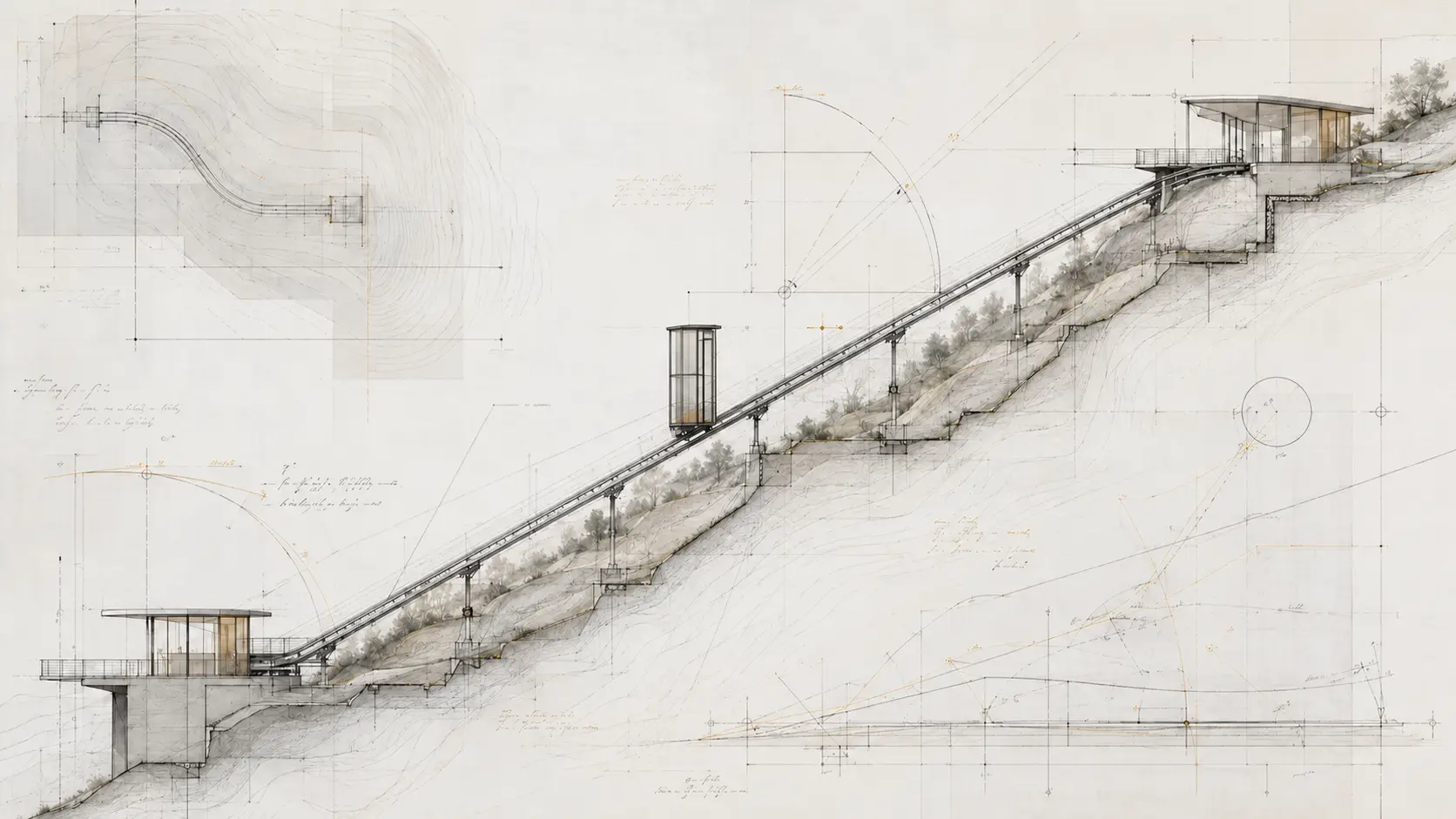
With or without an architect, a few well-chosen details can explain the route, intended use and principal interfaces before a more detailed study begins.
Begin with the needLevels to connect, intended users and the journeys that must actually work.
Use available documentsPhotographs, older plans and approximate dimensions may be enough to begin.
Coordinate progressivelyThe owner, designer and contractors share the same assumptions at the right time.
The starting point does not have to be an architect’s drawing. A general view of the site, photographs taken from the lower and upper levels, the points to connect and a description of daily journeys already provide a useful basis.
Where an architect, project manager or engineer is involved, this information may be complemented by a site plan, section, levels and constraints from other work packages. F. Labbé can then qualify a principle and identify what still needs to be surveyed, without turning an early sketch into a technical promise. The page on hillside access solutions helps distinguish the different families of equipment.

You do not need to wait for construction drawings. Documents should above all be clear, dated and consistent with one another.
Photographs, location plan, available section, levels, walls, terraces and features to preserve.
Departure and arrival points, possible stations, and the journeys before and after the inclined section.
Users, frequency, luggage or objects, accessibility expectations and operating conditions.
Access, neighbours, possible lifting methods, other contractors, programme and current project stage.
A section establishes the general geometry. Studies then define the route, stations, footprint, supports, clearances, protection and connections with finished levels. The drawing becomes a shared document for the owner, designer, workshop and site team.
This progression is essential in a bespoke project. It allows routes to be compared, associated works to be identified and the effect of a change to be understood before manufacturing.
The calculation uses horizontal distance and vertical rise to estimate the angle, gradient percentage and geometric length of a direct route. The full-page slope calculator then identifies subjects that still require survey and bespoke study.
approximately 33% gradient
Compare possible routes, intended use and the major site constraints.
Confirm geometry, footprint and the information needed to define the equipment.
Coordinate stations, structure, finished levels, power, water and technical access.
Validate documents, access, sequencing, protection and the conditions for site work.
The familiar name of a solution does not classify the equipment. Its use, technology, environment and operation determine which texts, processes and verifications must be examined with the competent project parties.
A few simple details are enough to understand the journey and prepare a useful first discussion.